Some time ago, OPSIS published descriptions on how some well-established types of gas analysers work, namely those based on spectrometers, interferometers, and tuneable diode lasers. They all utilize absorption of light to determine the concentrations of gaseous pollutants such as nitrogen oxides (NOX), sulfur dioxide (SO2), hydrogen chloride (HCl), ammonia (NH3), and many more. The same technology is used both for ambient air quality monitoring and for industrial applications. But how does a particulate monitor work?
First of all, we have to separate between particulates in ambient air and particulates, also referred to as dust, in industrial applications. The concentrations are hugely different and different types of monitoring techniques are usually applied. Let’s look at the filter sampling technique which is a common practice in ambient air quality monitoring, although it also has a few applications in industrial processes.
Measurement Principles
In ambient air sampling, there is usually an initial selection of particulate fraction, often excluding particles with average diameters greater than 10 or 2.5 µm, hence the naming “PM10” and “PM2.5”. This is achieved through the design of the air intakes, referred to as inlet heads or sampling heads. A carefully controlled stream of air is taken through the inlet head and is then forced through a filter. After the sampling period, the filter content is analysed.
Inlet Heads
The inlet head ensures that the desired particulate fraction is forwarded to the analyser while other (larger) particles are trapped and thereby not included in the measurement results. The head is a passive device, where the selection of particle size is caused by the air stream being forced through a tube system. Light and thereby small particles follow the air stream while heavier and thereby larger particles are trapped inside the head.
There are at least two groups of inlet heads: European (EU-style) and US EPA (US-style) heads. For each group, there are also different designs depending on which particulate fraction the head should select, and which airflow standard is used.
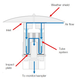
A European-style inlet head.
Filter Sampling
The sampling normally starts with a pristine filter being moved into the air flow. After a set sampling time, the now dust-laden filter is moved out of the stream for subsequent evaluation. The filters can be individuals mounted on filter holders but there are also designs based on long filter bands on reels which position is incremented as a new sampling periods start. The filter material is often made of Teflon, but other material like nitrocellulose and glass fibre can also be used.
Filter Analysis
In most cases, the sampling is followed by an automated measurement of the thickness of the particles on the filter. Such thickness is correlated with average density, and since the exposed filter area and the total air volume having passed the filter during the sampling is known, the particulate concentration can be established. A commonly applied method to measure the thickness is based on attenuation of beta rays (electrons).
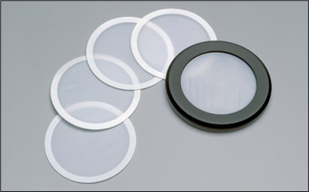
Standard filters for particulate sampling, 47 mm diameter.
Sampling on filters is a relatively slow process. The actual sampling typically runs for at least an hour and in many cases for an entire day (24 hours) and it then takes another one or a few hours to analyse the thickness of the sample. The upside is the preservation of the filter which allows subsequent analysis of the composition of particulates at a laboratory, mainly for establishing the constituents of the particles, in particular metal content. Metal content analysis is also the primary application of particulates/dust sampling in industrial processes.
Oscillating Tapered Elements
Another filter-based principle to measure ambient particulate concentrations is the tapered element oscillating microbalance (TEOM) method. A sample drawn through an inlet head is led to a particle filter mounted on top of a hollow glass tube through which the air flows. The lower end of the tube is firmly secured but the upper end with its filter can move freely and is made to vibrate at its natural frequency. As particles accumulate on the filter, the weight of the filter changes and so does the natural frequency of the glass tube. The frequency change over time is measured, which gives the accumulated particle weight and, in combination with the flow rate, the particulates concentration as a function of time.
The mass load on the filter must be monitored and the filter must be replaced manually before it is saturated. The interval depends on the dust concentrations in the ambient air but is typically monthly or shorter.
Optical Methods
With all this said about filter sampling, it should be noted that it is also quite common to measure particulate concentrations in ambient air with optical methods, and even more so in industrial applications. No filters are used, and measurement results are often provided in close-to real time.
Optical methods are addressed in another blog post – click here to continue reading >>
About the Author
Bengt Löfstedt
Operative Support, OPSIS AB